Running in AWS Environment
This page primarily explains how to run Spiderpool in an AWS environment and how to implement a complete Underlay solution.
Background
There are many public cloud providers available today, such as Alibaba Cloud, Huawei Cloud, Tencent Cloud, AWS, etc. However, it is difficult to run mainstream CNI plugins in an Underlay network mode on these cloud platforms. Instead, proprietary CNI plugins provided by each cloud provider must be used, resulting in a lack of unified public cloud Underlay solutions. This document introduces a Underlay network solution, called Spiderpool, suitable for any public cloud environment, especially in hybrid cloud scenarios where a unified CNI solution facilitates multi-cloud management.
Why Spiderpool
-
Spiderpool is an underlay and RDMA network solution for the Kubernetes. It enhances the capabilities of Macvlan CNI, IPvlan CNI, SR-IOV CNI fulfills various networking needs, and supports to run on bare metal, virtual machine, and public cloud environments. Spiderpool delivers exceptional network performance.
-
aws-vpc-cni Networking plugin for pod networking in Kubernetes using Elastic Network Interfaces on AWS.
aws-vpc-cni is an underlay network solution provided by AWS for public cloud, but it cannot meet complex network requirements. The following is a comparison of some functions between spiderpool and aws-cni. The related functions of Spiderpool will be demonstrated in subsequent chapters:
| Feature comparison | aws-vpc-cni | Spiderpool + IPvlan |
|---|---|---|
| Multiple Underlay NICs | ❌ | ✅ (Multiple Underlay NICs across subnets) |
| Custom routing | ❌ | ✅ route |
| Dual CNI collaboration | Supports multiple CNI NIC but does not support routing coordination | ✅ support rdma |
| network policy | ✅ aws-network-policy-agent | ✅ cilium-chaining |
| clusterIP | ✅ (kube-proxy) | ✅ (kube-proxy and ebpf two methods) |
| Bandwidth | ❌ | ✅ Bandwidth management |
| metrics | ✅ | ✅ |
| Dual stack | IPv4 only, IPv6 only, dual stack is not supported | IPv4 only, IPv6 only, dual stack |
| Observability | ❌ | ✅(with cilium hubble, kernel>=4.19.57) |
| Multi-cluster | ❌ | ✅ Submariner |
| Paired with AWS layer 4/7 load balancing | ✅ | ✅ |
| Kernel limit | None | >= 4.2 (IPvlan kernel limit) |
| Forwarding principle | underlay pure routing layer 3 forwarding | IPvlan layer 2 |
| multicast | ❌ | ✅ |
| Cross vpc access | ✅ | ✅ |
Solutions Provided by Spiderpool for Limitations in AWS
Spiderpool can run on public cloud environments based on the ipvlan Underlay CNI and provide features such as node topology and MAC address validity. Its implementation principle is as follows:
-
Underlay networking is used in public clouds, but each network interface card (NIC) on each cloud server can only be assigned a limited number of IP addresses. When an application is running on a cloud server, it needs to synchronously obtain valid IP addresses assigned to different NICs in the VPC network to enable communication. Based on the IP assignment characteristics mentioned above, Spiderpool's CRD (Custom Resource Definition):
SpiderIPPoolcan be configured with nodeName and multusName to achieve node topology functionality. By using IP pools and the affinity between nodes and ipvlan Multus configurations, Spiderpool maximizes the utilization and management of available IP addresses on nodes, assigns valid IP addresses to applications, and enables free communication within the VPC network, including communication between Pods and between Pods and cloud servers. -
In the VPC network of public clouds, due to network security control and packet forwarding principles, when network datagrams contain MAC and IP addresses unknown to the VPC network, they cannot be correctly forwarded. For example, Underlay CNI plugins based on Macvlan and OVS principles generate new MAC addresses for Pod interfaces, causing communication issues. To address this problem, Spiderpool can be used in conjunction with ipvlan CNI. ipvlan operates at Layer 3, eliminating the need for Layer 2 broadcast and avoiding the generation of new MAC addresses. It keeps the MAC addresses consistent with the parent interface. Therefore, ipvlan can solve the issue of MAC address validity in public clouds.
Implementation Requirements
-
When using ipvlan as the cluster CNI, the kernel version must be greater than 4.2.
-
Helm is already installed. You can refer to Helm for installation instructions.
-
Basic understanding of AWS VPC Public & Private Subnets.
In AWS VPC, a subnet created with an outbound route of 0.0.0.0/0, ::/0 to an Internet Gateway is considered a public subnet, while a subnet without this outbound route is considered a private subnet.
Steps
AWS Environment
-
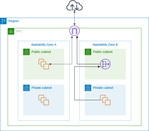
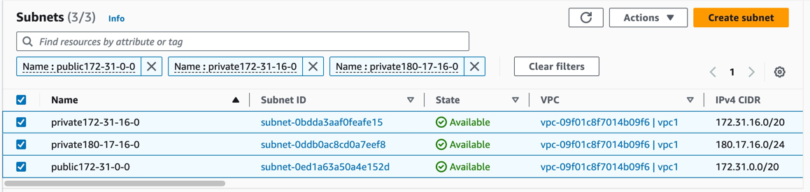
Create a public subnet and a private subnet under the VPC, and create virtual machines (VMs) under the private subnet, as shown in the diagram:
In this example, we will create one public subnet and two private subnets under the same VPC (please deploy the subnets in different availability zones). Then, we will create an AWS EC2 instance as a jump host under the public subnet. Finally, we will create AWS EC2 instances under the two private subnets to deploy the Kubernetes cluster.
-
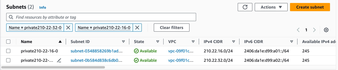
Create two additional private subnets to provide a second network interface (NIC) for the instances (please deploy the subnets in the same availability zones as the instances), as shown in the diagram:
-
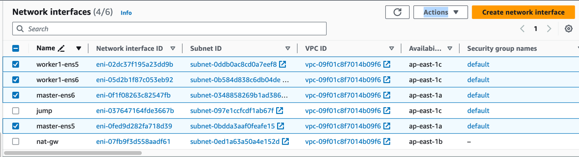
Assign some secondary private IP addresses to each NIC of the instances, as shown in the diagram:
According to AWS EC2 instance types, there are limitations on the number of NICs and secondary IP addresses that can be assigned to each NIC. To make full use of instance resources for application deployment, we choose to bind two NICs and corresponding secondary IP addresses to the instances.
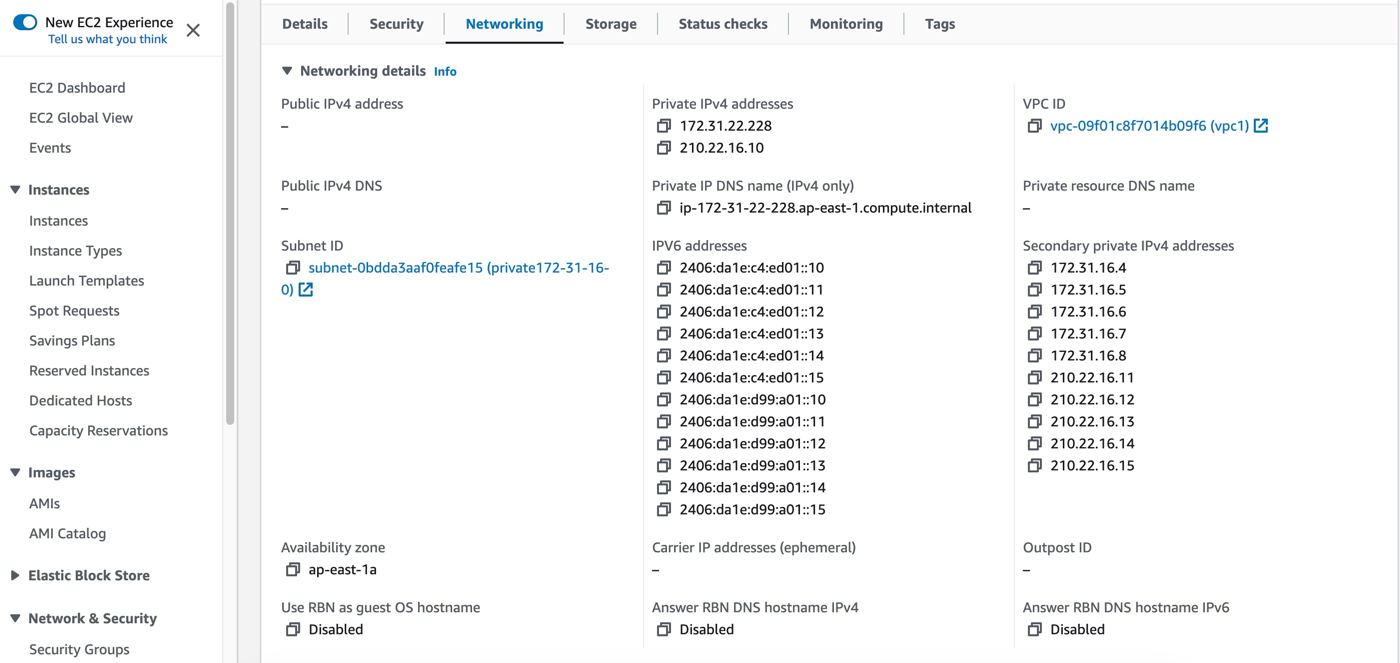
| Node | ens5 primary IP | ens5 secondary IPs | ens6 primary IP | ens6 secondary IPs | |---------|-----------------|---------------------------|-----------------|---------------------------| | master | 172.31.22.228 | 172.31.16.4-172.31.16.8 | 210.22.16.10 | 210.22.16.11-210.22.16.15 | | worker1 | 180.17.16.17 | 180.17.16.11-180.17.16.15 | 210.22.32.10 | 210.22.32.11-210.22.32.15 | -
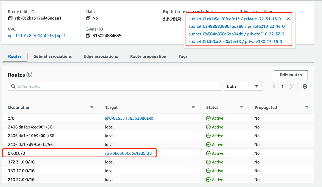
Create an AWS NAT Gateway. The NAT Gateway allows instances in the VPC private subnet to connect to services outside the VPC. It enables outbound traffic for the cluster. Refer to the NAT Gateway documentation for instructions on creating a NAT Gateway, as shown in the diagram:
Create a NAT Gateway in the public subnet
public-172-31-0-0and configure the route table of the private subnet with an outbound route of 0.0.0.0/0 and the NAT Gateway as the next-hop. (Note that IPv6 addresses are globally unique addresses assigned by AWS and can directly access the Internet via the Internet Gateway.)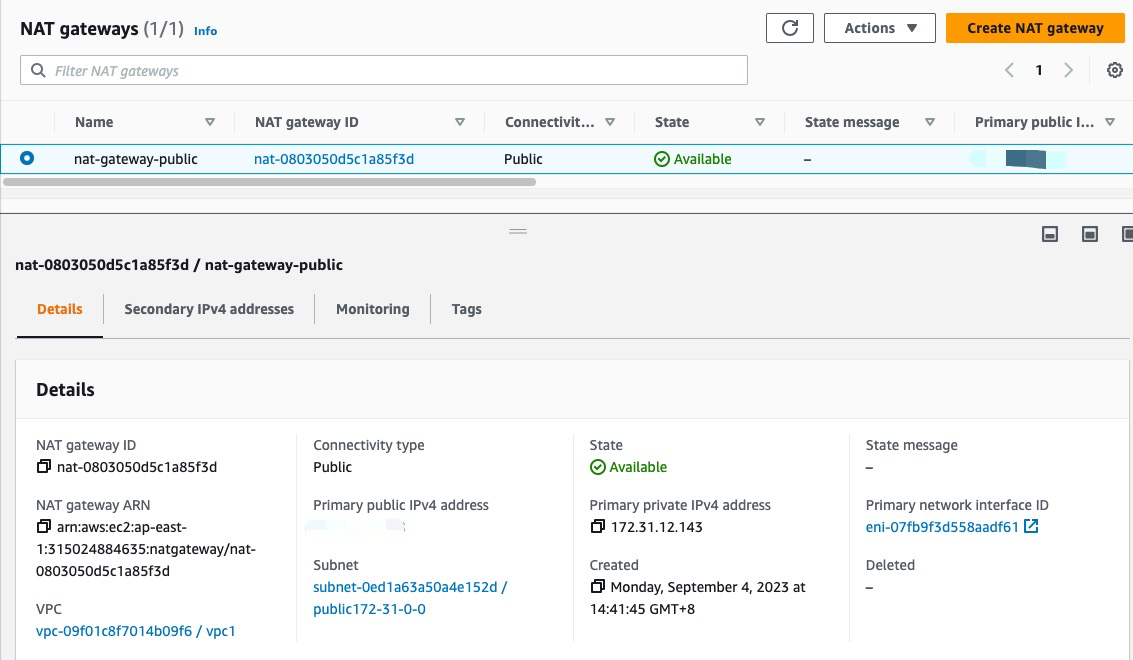
-
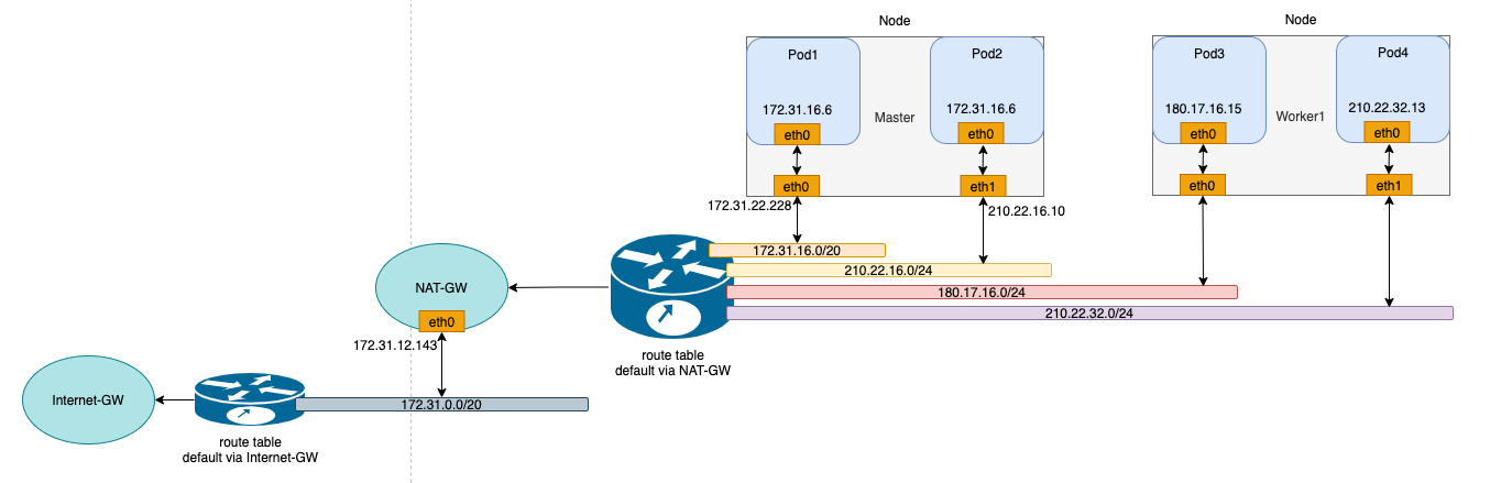
Use the configured VMs to set up a Kubernetes cluster. The available IP addresses for the nodes and the network topology of the cluster are as follows:
Install Spiderpool
Install Spiderpool using Helm:
helm repo add spiderpool https://spidernet-io.github.io/spiderpool
helm repo update spiderpool
helm install spiderpool spiderpool/spiderpool --namespace kube-system --set ipam.enableStatefulSet=false --set multus.multusCNI.defaultCniCRName="default/ipvlan-ens5"
Note
- If you are using servers from a cloud provider in mainland China, you can specify the parameter
--set global.imageRegistryOverride=ghcr.m.daocloud.ioto help you pull images faster. - Spiderpool can assign fixed IP addresses to replicas of applications with the controller type
StatefulSet. In public cloud Underlay network scenarios, cloud instances can only use limited IP addresses. When replicas of StatefulSet applications are moved to other nodes, the original fixed IP addresses become invalid on the new nodes, causing network unavailability for the new Pods. To address this issue, setipam.enableStatefulSettofalseto disable this feature. - Specify the default CNI NetworkAttachmentDefinition instance used by Multus using
multus.multusCNI.defaultCniCRName. If themultus.multusCNI.defaultCniCRNameoption is not empty, an empty NetworkAttachmentDefinition instance corresponding to it will be automatically generated after installation. If themultus.multusCNI.defaultCniCRNameoption is empty, an attempt will be made to create the proper NetworkAttachmentDefinition instance using the first CNI configuration in the/etc/cni/net.ddirectory. If that fails, a NetworkAttachmentDefinition instance nameddefaultwill be generated to complete the installation of Multus.
Install CNI Configuration
Spiderpool simplifies the writing of JSON-formatted Multus CNI configurations by providing the SpiderMultusConfig CR to automatically manage Multus NetworkAttachmentDefinition CRs. Based on the network interfaces created during the process of creating AWS EC2 instances, the following example shows the SpiderMultusConfig configuration for each network interface used to run the ipvlan CNI:
IPVLAN_MASTER_INTERFACE0="ens5"
IPVLAN_MULTUS_NAME0="ipvlan-$IPVLAN_MASTER_INTERFACE0"
IPVLAN_MASTER_INTERFACE1="ens6"
IPVLAN_MULTUS_NAME1="ipvlan-$IPVLAN_MASTER_INTERFACE1"

cat <<EOF | kubectl apply -f -
apiVersion: spiderpool.spidernet.io/v2beta1
kind: SpiderMultusConfig
metadata:
  name: ${IPVLAN_MULTUS_NAME0}
  namespace: default
spec:
  cniType: ipvlan
  ipvlan:
    master:
    - ${IPVLAN_MASTER_INTERFACE0}
---
apiVersion: spiderpool.spidernet.io/v2beta1
kind: SpiderMultusConfig
metadata:
  name: ${IPVLAN_MULTUS_NAME1}
  namespace: default
spec:
  cniType: ipvlan
  ipvlan:
    master:
    - ${IPVLAN_MASTER_INTERFACE1}
EOF
In the example provided in this document, using the above configuration, create the following two ipvlan SpiderMultusConfig instances. These instances will automatically generate the proper Multus NetworkAttachmentDefinition CRs for the host's eth5 and eth6 network interfaces.
$ kubectl get spidermultusconfigs.spiderpool.spidernet.io -A
NAMESPACE     NAME                AGE
default       ipvlan-ens5   8d
default       ipvlan-ens6   8d

$ kubectl get network-attachment-definitions.k8s.cni.cncf.io -A
NAMESPACE     NAME                AGE
default       ipvlan-ens5   8d
default       ipvlan-ens6   8d
Create IP Pools
The Spiderpool CRD, SpiderIPPool, provides the nodeName, multusName, and ips fields:
-
nodeName: This field restricts the current SpiderIPPool resource to only be applicable to specific nodes. If the node where the Pod is located matches thenodeName, an IP can be successfully allocated from the SpiderIPPool. If the node does not match thenodeName, no IP can be allocated from the SpiderIPPool. When this field is empty, it indicates that the current Spiderpool resource is applicable to all nodes in the cluster. -
multusName: Spiderpool integrates deeply with Multus CNI to handle multi-NIC scenarios. WhenmultusNameis not empty, SpiderIPPool will use the corresponding Multus CR instance to configure the network for Pods. If the Multus CR corresponding tomultusNamedoes not exist, Spiderpool will not be able to specify the Multus CR for Pods. WhenmultusNameis empty, Spiderpool does not restrict the Multus CR used by Pods. -
spec.ips: Based on the network interfaces and secondary IP addresses of the AWS EC2 instances mentioned earlier, the values ofspec.ipsmust fall within the range of secondary private IP addresses of the proper host specified bynodeName. Each IP address should correspond to a unique instance interface.
Based on the network interfaces and corresponding secondary IP information of the AWS EC2 instances mentioned in the AWS Environment section, use the following YAML to create a SpiderIPPool for each network interface (ens5 and ens6) of each node. These SpiderIPPools will provide IP addresses for Pods on different nodes.
$ cat <<EOF | kubectl apply -f -
apiVersion: spiderpool.spidernet.io/v2beta1
kind: SpiderIPPool
metadata:
  name: master-v4-ens5
spec:
  subnet: 172.31.16.0/20
  ips:
    - 172.31.16.4-172.31.16.8
  gateway: 172.31.16.1
  default: true
  nodeName: ["master"]
  multusName: ["default/ipvlan-ens5"]
---
apiVersion: spiderpool.spidernet.io/v2beta1
kind: SpiderIPPool
metadata:
  name: master-v4-ens6
spec:
  subnet: 210.22.16.0/24
  ips:
    - 210.22.16.11-210.22.16.15
  gateway: 210.22.16.1
  default: true
  nodeName: ["master"]
  multusName: ["default/ipvlan-ens6"]
---
apiVersion: spiderpool.spidernet.io/v2beta1
kind: SpiderIPPool
metadata:
  name: worker1-v4-ens5
spec:
  subnet: 180.17.16.0/24
  ips:
    - 180.17.16.11-180.17.16.15
  gateway: 180.17.16.1
  default: true
  nodeName: ["worker1"]
  multusName: ["default/ipvlan-ens5"]
---
apiVersion: spiderpool.spidernet.io/v2beta1
kind: SpiderIPPool
metadata:
  name: worker1-v4-ens6
spec:
  subnet: 210.22.32.0/24
  ips:
    - 210.22.32.11-210.22.32.15
  gateway: 210.22.32.1
  default: true
  nodeName: ["worker1"]
  multusName: ["default/ipvlan-ens6"]
EOF
Create Applications
In the following example YAML, a Deployment application will be created with the following configuration:
v1.multus-cni.io/default-network: Specifies the CNI configuration for the application. In the example, the application is configured to use the ipvlan configuration corresponding to the host's ens5 interface, and it will automatically select the subnet corresponding to the default SpiderIPPool resource.
cat <<EOF | kubectl create -f -
apiVersion: apps/v1
kind: Deployment
metadata:
  name: nginx-lb-1
spec:
  selector:
    matchLabels:
      run: nginx-lb-1
  replicas: 2
  template:
    metadata:
      annotations:
        v1.multus-cni.io/default-network: "default/ipvlan-ens5"
      labels:
        run: nginx-lb-1
    spec:
      containers:
      - name: nginx-lb-1
        image: nginx
        ports:
        - containerPort: 80
EOF
To check the running status of Pods, we can see that we have one Pod running on each of the two nodes, and they are using IP addresses corresponding to the secondary IP of the first network interface of the host.
$ kubectl get po -owide
NAME                          READY   STATUS    RESTARTS   AGE   IP             NODE      NOMINATED NODE   READINESS GATES
nginx-lb-1-55d4c48fc8-skrxh   1/1     Running   0          5s    172.31.16.5    master    <none>           <none>
nginx-lb-1-55d4c48fc8-jl8b9   1/1     Running   0          5s    180.17.16.14   worker1   <none>           <none>
Test East-West Connectivity in the Cluster
-
Test communication between Pods and the host:
-
Test communication between Pods across nodes and subnets:
-
Test communication between Pods and ClusterIP:
Test North-South Connectivity in the Cluster
Outbound Traffic from Pods in the Cluster
With the AWS NAT Gateway created earlier in the AWS Environment section, the private network in our VPC can now access the internet.
Ingress Traffic for Load Balancing (Optional)
Deploy AWS Load Balancer Controller
AWS provides a load balancing service called "Elastic Load Balancer" (ELB) with two modes: Network Load Balancer (NLB) and Application Load Balancer (ALB), corresponding to Layer 4 and Layer 7, respectively. The aws-load-balancer-controller is an AWS-provided component for integrating Kubernetes with AWS load balancing services, enabling Kubernetes Service LoadBalancer and Ingress functionality. In this document, we will use this component along with AWS infrastructure to achieve load balancing for inbound traffic. The following steps demonstrate the deployment of aws-load-balancer-controller using version v2.6. Please refer to the aws-load-balancer-controller documentation to complete the deployment of aws-load-balancer-controller.
-
Configure
providerIDfor cluster nodes:Be sure to set the
providerIDfor each node in Kubernetes. You can do this in two ways:- You can find the instance ID of each instance in the AWS EC2 dashboard.
- Use the AWS CLI to query the instance ID:
aws ec2 describe-instances --query 'Reservations[*].Instances[*].{Instance:InstanceId}'.
-
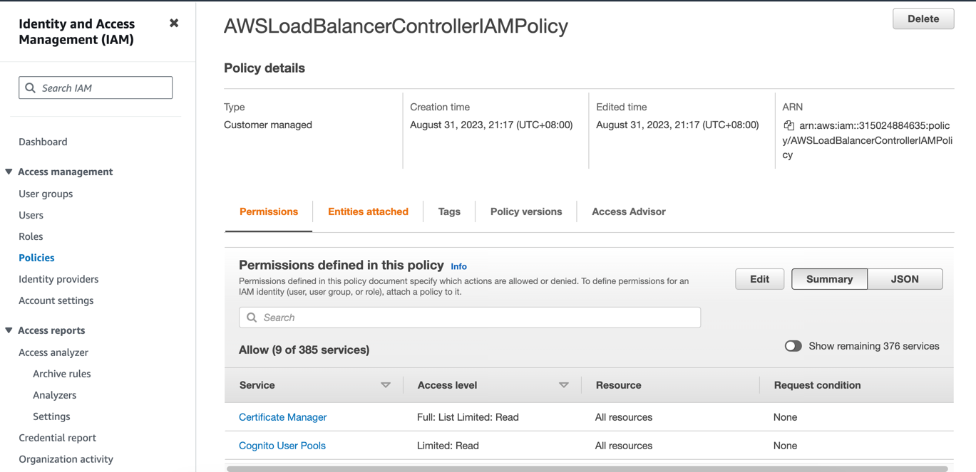
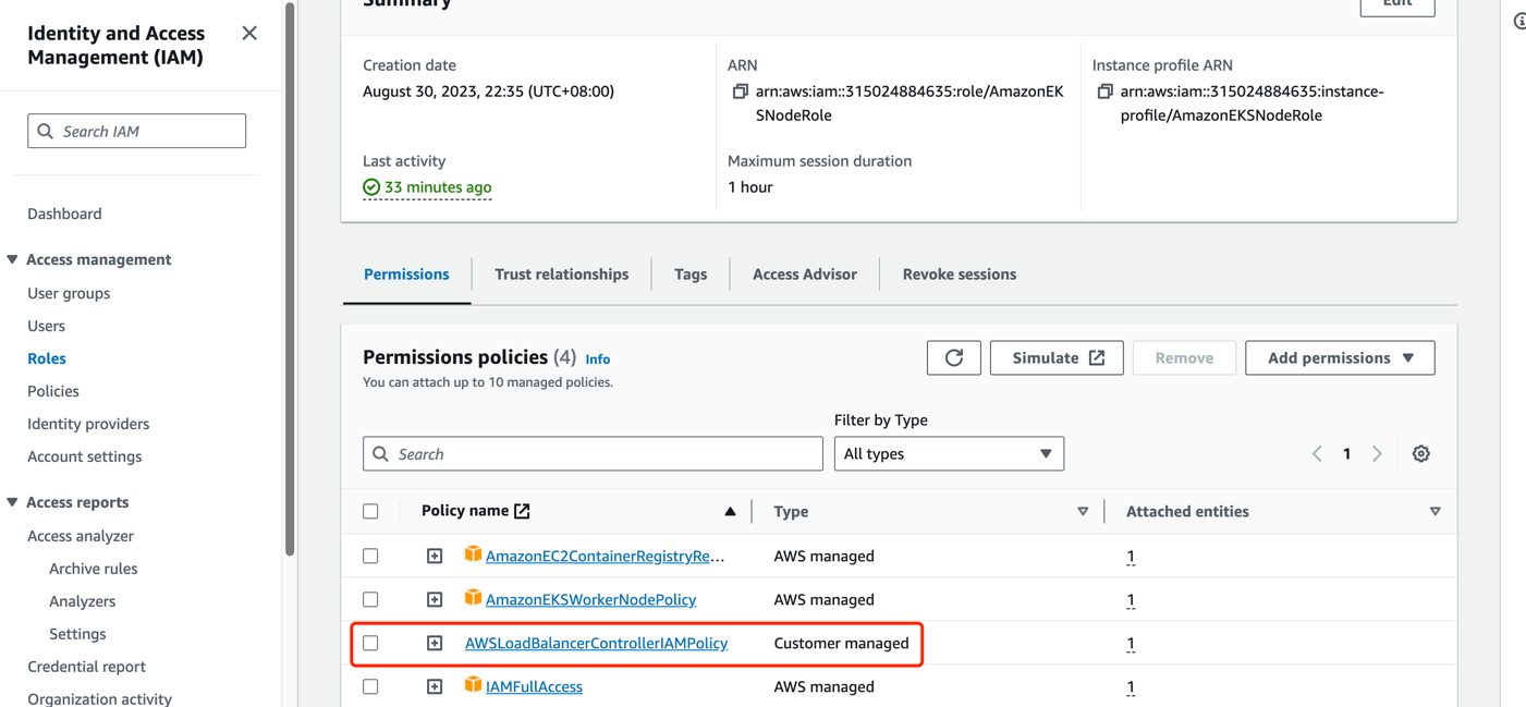
Add a policy to the IAM role used by AWS EC2 instances:
- Since the
aws-load-balancer-controllerruns on each node and requires access to the AWS NLB/ALB APIs, it needs authorization for NLB/ALB-related requests in AWS IAM. Since we have a self-managed cluster, we need to use the IAM role of the nodes themselves for authorization. For more details, refer to the aws-load-balancer-controller IAM. - Run
curl -o iam-policy.json https://raw.githubusercontent.com/kubernetes-sigs/aws-load-balancer-controller/v2.6.0/docs/install/iam_policy.json. - Create a new policy in the AWS IAM dashboard using the JSON content obtained in the previous step. Associate this policy with the IAM role of your virtual machine instance.
- Since the
-
Create a public subnet in the availability zone where your AWS EC2 instance is located and tag it for automatic discovery.
- For ALB usage, you need at least two subnets across different availability zones. For NLB usage, you need at least one subnet. Refer to the Subnet Discovery documentation for more details.
- For LBs with public internet access, you need to tag the public subnet in the availability zone where your instance is located with
kubernetes.io/role/elb:1. For LBs with inter-VPC access, create a private subnet and tag it withkubernetes.io/role/internal-elb:1. Please create the required subnets based on the AWS Environment section:
- For LBs exposed to the internet, create a public subnet: In the AWS VPC Dashboard Subnets section, select "Create subnet" and choose the same availability zone as your EC2 instance. Then, associate the subnet with the Main route table in the Route tables section. (Note: The Main route table should have a default route of 0.0.0.0/0 with the Internet Gateway as the next hop. If it's missing, please create the route rule manually).
- Create a new route table in the AWS VPC Dashboard Route tables section and configure the default route (0.0.0.0/0) to use the NAT Gateway as the next hop, and (::/0) to use the Internet Gateway as the next hop.
- For LBs with inter-VPC access, create a private subnet: In the AWS VPC Dashboard Subnets section, select "Create subnet" and choose the same availability zone as your EC2 instance. Then, associate the subnet with the route table created in the previous step.
-
Install
aws-load-balancer-controllerusing Helm (versionv2.6in this example). -
Verify the installation of
aws-load-balancer-controller:
Create a Load Balancer for Application Access
In the previous section, we created the application. Now we will create a Kubernetes Service of type LoadBalancer for it. If you have a dual-stack requirement, uncomment the service.beta.kubernetes.io/aws-load-balancer-ip-address-type: dualstack annotation.
cat <<EOF | kubectl create -f -
apiVersion: v1
kind: Service
metadata:
  name: nginx-svc-lb-1
  labels:
    run: nginx-lb-1
  annotations:
    service.beta.kubernetes.io/aws-load-balancer-nlb-target-type: ip
    service.beta.kubernetes.io/aws-load-balancer-scheme: internet-facing
    service.beta.kubernetes.io/aws-load-balancer-target-group-attributes: preserve_client_ip.enabled=true
    # service.beta.kubernetes.io/aws-load-balancer-ip-address-type: dualstack
spec:
  type: LoadBalancer
  ports:
  - port: 80
    protocol: TCP
  selector:
    run: nginx-lb-1

EOF
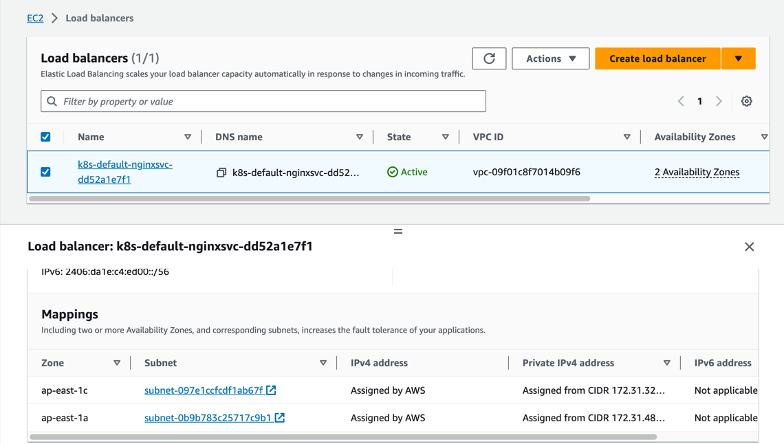
We can now see that an NLB has been created and is accessible in the AWS EC2 Load Balancing section.
- NLB also supports creating LB in instance mode, simply modify the annotation
service.beta.kubernetes.io/aws-load-balancer-nlb-target-type. However, due to the use ofservice.spec.externalTraffic=Localmode, which does not support node migration, it is not recommended.- The annotation
service.beta.kubernetes.io/load-balancer-source-rangescan be used to restrict access to specific source IP ranges. Note that this feature is associated with theservice.beta.kubernetes.io/aws-load-balancer-ip-address-typeannotation. If the default is IPv4, the value defaults to0.0.0.0/0. If it is dualstack, the default is0.0.0.0/0, ::/0.- The annotation
service.beta.kubernetes.io/aws-load-balancer-schemecan be used to specify whether the NLB should be exposed for public internet access or for inter-VPC access. The default value isinternalfor inter-VPC access.- The annotation
service.beta.kubernetes.io/aws-load-balancer-target-group-attributes: preserve_client_ip.enabled=trueprovides the functionality to preserve the client source IP.
Create an Ingress for Application Access
Next, we will create a Kubernetes Ingress resource using the second network interface attached to the AWS EC2 instance. If you have a dual-stack requirement, uncomment the alb.ingress.kubernetes.io/ip-address-type: dualstack annotation.
apiVersion: apps/v1
kind: Deployment
metadata:
  name: nginx-ingress
spec:
  selector:
    matchLabels:
      run: nginx-ingress
  replicas: 2
  template:
    metadata:
      annotations:
        v1.multus-cni.io/default-network: "default/ipvlan-ens6"
      labels:
        run: nginx-ingress
    spec:
      containers:
      - name: nginx-ingress
        image: nginx
        ports:
        - containerPort: 80
---
apiVersion: v1
kind: Service
metadata:
  name: nginx-svc-ingress
  labels:
    run: nginx-ingress
spec:
  type: NodePort
  ports:
  - port: 80
    protocol: TCP
  selector:
    run: nginx-ingress
---
apiVersion: apps/v1
kind: Deployment
metadata:
  name: echoserver
spec:
  selector:
    matchLabels:
      app: echoserver
  replicas: 2
  template:
    metadata:
      annotations:
        v1.multus-cni.io/default-network: "default/ipvlan-ens6"
      labels:
        app: echoserver
    spec:
      containers:
      - image: k8s.gcr.io/e2e-test-images/echoserver:2.5
        imagePullPolicy: Always
        name: echoserver
        ports:
        - containerPort: 8080
---
apiVersion: v1
kind: Service
metadata:
  name: echoserver
spec:
  ports:
    - port: 80
      targetPort: 8080
      protocol: TCP
  type: NodePort
  selector:
    app: echoserver
---
apiVersion: networking.k8s.io/v1
kind: Ingress
metadata:
  name: k8s-app-ingress
  annotations:
    alb.ingress.kubernetes.io/target-type: ip
    alb.ingress.kubernetes.io/scheme: internet-facing
    # alb.ingress.kubernetes.io/ip-address-type: dualstack
spec:
  ingressClassName: alb
  rules:
    - http:
        paths:
          - path: /
            pathType: Exact
            backend:
              service:
                name: nginx-svc-ingress
                port:
                  number: 80
    - http:
        paths:
          - path: /echo
            pathType: Exact
            backend:
              service:
                name: echoserver
                port:
                  number: 80
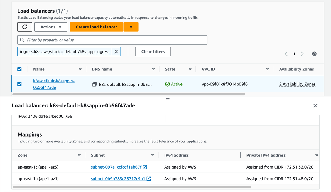
We can now see that an ALB has been created and is accessible in the AWS EC2 Load Balancing section.
- ALB also supports creating LB in instance mode. To use this mode, modify the
alb.ingress.kubernetes.io/target-typeannotation. However, due to the use ofservice.spec.externalTraffic=Localmode, which does not support node migration, it is not recommended.- When using ALB in instance mode, you need to specify the service as NodePort mode.
- The annotation
alb.ingress.kubernetes.io/inbound-cidrscan be used to restrict access to specific source IP ranges. (Note that this feature is associated with thealb.ingress.kubernetes.io/ip-address-typeannotation. If the default is IPv4, the value defaults to0.0.0.0/0. If it is dualstack, the default is0.0.0.0/0, ::/0).- The annotation
alb.ingress.kubernetes.io/schemecan be used to specify whether the ALB should be exposed for public internet access or for inter-VPC access. The default value isinternalfor inter-VPC access.- If you want to integrate multiple Ingress resources to share the same entry point, you can configure the
alb.ingress.kubernetes.io/group.nameannotation to specify a name. (Note: Ingress resources that do not specify this annotation will not belong to any IngressGroup and will be treated as an "implicit IngressGroup" composed of the Ingress itself).- If you want to specify the host for an Ingress, you need to use externalDNS. Refer to the externalDNS configuration for more details.